- CYPE >
- english >
- new features >
- 2011 >
- cypecad

- New CYPECAD modules
- Joints V. Flat trusses with hollow structural sections (as of the 2011.a version)
- Advanced design of surface foundations (as of the 2011.a version)
- Matrix foundation calculation (as of the 2011.a version)
- Different building use for each floor group (as of the 2011.a version)
- Material textures in 3D views (as of the 2011.a version)
- Export to Tekla Structures
- Other new features of CYPECAD
- Lateral buckling of the top flange of steel beams (as of the 2011.a version)
- Plane assigning to the tops of walls (as of the 2011.a version)
- Object snap tracking (as of the 2011.a version)
- Edition resources (as of the 2011.a version)
- More new features
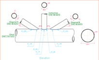
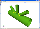
Joints V. Flat trusses with hollow structural sections (as of the 2011.a version)
The Joints V. Flat trusses with hollow structural sections module for CYPECAD, its Integrated 3D structures and Metal 3D, carries out an automatic analysis and design of coplanar hollow structural section connections, like those which are usually provided in flat trusses.
More information on this module can be found at: Joints V. Flat trusses with hollow structural sections.
Advanced design of surface foundations (as of the 2011.a version)
The Advanced design of surface foundations module complements the Footings and Pile caps modules when these are used in CYPECAD. Allows for the design of foundations composed of footings and pile caps with special element intersections (strap and tie beam intersections), geometrical trimming of footings, and application of line, point and surface loads on footings, pile caps and strap and tie beams. In the case of Metal 3D, this module only allows for trimming of the footing geometry to be carried out.
More information on this module can be found at: Advanced design of surface foundations
Matrix foundation calculation (as of the 2011.a version)
Changes have been carried out in the calculation method used to obtain the forces of footings “with external fixity”, for footings, pile caps, strap and tie beams.
The current design can differ from previous versions. Now, once the reactions at the base of the supporting elements of the structure are obtained (columns, shear walls and walls), a model is created will all the foundation elements “with external fixity” and its beams, represented by its stiffness matrix. The stiffness matrix, together with the loadcases defined as loads acting on the foundation (reactions that have been obtained), is resolved using frontal methods to obtain the displacements and forces of all the elements. By doing this, the stiffness of all the elements intervene and interact with one another.
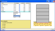
Different building use for each floor group (as of the 2011.a version)
Now in CYPECAD, different use categories can be defined for each floor group of the structure. Examples of use categories include: dwellings, shops, warehouses, garages, etc. The number of use categories the program allows to choose amongst depends on the selected code. For example, the use categories for the Eurocode are:
- A. Domestic and household
- B. Offices
- C. Meeting areas
- D. Shops
- E. Warehouses
- F. Vehicle weight <= 30 kN
- G. 30 kN < vehicle weight <= 160 kN
- H. Roofs
For the program, a use category consists of a group of live loadcases, be they automatic or additional, which combine with the other loadcases that have been defined in the job with the same combination coefficients.
This way, the live load combinations for each use category can be analysed correctly amongst all the use categories and the remaining loadcases of the job for which different use categories exist per floor.
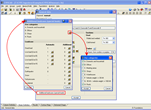
The use categories can be selected in the Additional loadcases (special loads) dialogue box within the General data window (Job > General data > Additional loadcases (special loads)). The categories that are selected in this dialogue box are assigned to each floor group in the Edit groups dialogue box which opens by selecting the Loads menu within the Beam Definition tab > Loads in groups or in the Column Definition tab > Floors/Groups > Edit groups.
Different use categories can also be defined for a floor group. To do so, simply do not introduce a live load for the group and once the geometry of the floor group has been defined, introduce the live loads at different positions on the group, assigned to the corresponding loadcase.
The user should bear in mind that the more use categories are defined for a job, the more loadcase combinations the program will create, and so, the time taken to analyse the job will be substantially longer.
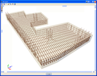
Material textures in 3D views (as of the 2011.a version)
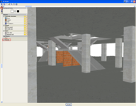
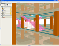
As of the 2011.a version, the 3D views of CYPECAD and Metal 3D contain a new option which displays elements with textures resembling the real colours of the material they are made out of.
More information can be found in the Material textures in 3D views section of the New features of the 2011 version website.
The following elements have been implemented when exporting to Tekla structures:
- Concrete beams and columns of CYPECAD, and concrete bars of Metal 3D and integrated 3D structures of CYPECAD. The elements that are exported have rectangular, circular, T or L sections.
- Special extruded aluminium sections
- Trims at hollow section ends processed by the new Joints V module.
These elements are exported as macros type “Tube-Saddle+Hole” for versions 15.0 SR1 and 16.0 of Tekla Structures.
Lateral buckling of the top flange of steel beams (as of the 2011.a version)
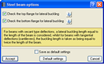
In previous versions, CYPECAD checked the bottom flange of steel beams not supporting floor slabs on that flange along their entire length, such as for example: beams below slabs, isolated beams, beams next to openings, or beams whose top flange projects above the floor slab.
Checking of both webs is activated in the Options for steel beams dialogue box which can be accessed from the Job menu in the Beam Definition tab > Beam options > Steel beam options.
Plane assigning to the tops of walls (as of the 2011.a version)
Horizontal or sloped planes defined in the Sloped floor slabs/El. Changes (Column Definition tab > Groups > Sloped floor slabs/ El. Changes) can now be assigned to the tops of walls. This way, the user can assign an elevation change or a slope to the top of a wall even if it does not support a floor slab.
Object snap tracking (as of the 2011.a version)
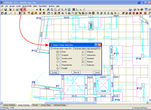
New object snap tracking options have been included in the Object snap selection box (perpendicular, parallel and extension) to be used with DXF and DWG templates.
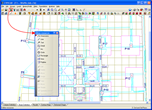
Edition resources (as of the 2011.a version)
Two new options have been added to the Edition resources dialogue box:
- Circle
Draws a circle without dimensions by indicating the radius or diameter - Polyline
Draws an open or closed polyline
Tel. USA (+1) 202 569 8902 // UK (+44) 20 3608 1448 // Spain (+34) 965 922 550 - Fax (+34) 965 124 950