- CYPE >
- english >
- new features >
- 2011 >
- metal 3d

and Integrated 3D structures of CYPECAD
- New Metal 3D modules
- Joints V. Flat trusses with hollow structural sections (as of the 2011.a version)
- Advanced design of surface foundations (as of the 2011.a version)
- Special extruded aluminium sections (as of the 2011.a version)
- Ties (as of the 2011.a version)
- Material textures in 3D views (as of the 2011.a version)
- Export to Tekla Structures
- Other new features of Metal 3D
- Improvements in the definition of lateral buckling moment coefficients (as of the 2011.a version)
- Faster seismic analysis (as of the 2011.a version)
- More new features
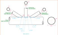
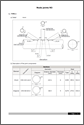
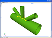
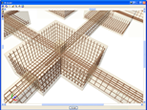
Joints V. Flat trusses with hollow structural sections (as of the 2011.a version)
The Joints V. Flat trusses with hollow structural sections module for CYPECAD, its Integrated 3D structures and Metal 3D, carries out an automatic analysis and design of coplanar hollow structural section connections, like those which are usually provided in flat trusses.
More information on this module can be found at: Joints V. Flat trusses with hollow structural sections.
Advanced design of surface foundations (as of the 2011.a version)
The Advanced design of surface foundations module complements the Footings and Pile caps modules when these are used in CYPECAD. Allows for the design of foundations composed of footings and pile caps with special element intersections (strap and tie beam intersections), geometrical trimming of footings, and application of line, point and surface loads on footings, pile caps and strap and tie beams. In the case of Metal 3D, this module only allows for trimming of the footing geometry to be carried out.
More information on this module can be found at: Advanced design of surface foundations
Special extruded aluminium sections (as of the 2011.a version)
The aluminium extrusion process has the advantage that as well as being able to obtain standard transverse aluminium alloy sections, specific designs can also be obtained. As of previous versions, the program has allowed users to design structures using standard extruded aluminium sections, i.e. those that are usually found in a manufacturer’s catalogue. As of the 2011.a version, one of the new features is the Extruded aluminium section editor, which allows for the design and check of aluminium alloy bars with specific transverse sections.
The Special aluminium section option has been included in the Describe section dialogue box (Bar > Describe section > select the bar on screen > right click with mouse button > Special aluminium section). Upon clicking the button, a dialogue box opens with options to create, copy, edit and manage a library of special extruded aluminium sections. Using the create button (or edit button, once special sections have been defined), the extruded aluminium section editor is displayed on screen.
The specific design of the section increases the range of available transverse sections, allowing for an optimum combination which simplifies the constructions process of the structure, with mechanical properties which maximise the resistance effectiveness with minimum weight. The program also offers the possibility of stiffened sections without having to use composite sections, which avoids having to weld or bolt the components.
Using the extruded aluminium sections editor, any section can be created: open, with cells, made up of thin walled flat elements… and used in the structural analysis to proceed with the resistance calculation, including the corresponding check reports.
The editor offers information on the mechanical and torsional properties of the gross section, required for the structural analysis, which is updated after any modifications have been carried out. Properties displayed include the section’s area, moment and product of inertia, torsion module, warping constant and shear centre coordinates.
Using the calculated resistance of the sections created with the editor, the section is checked for the forces derived from the structural analysis. The analysis incorporates an automatic calculation of the section’s susceptibility against the local buckling of the thin walled elements making up the transverse section, assuming each one buckles independently. The local buckling coefficient which affects the slenderness parameter of each element can be edited and so be able to consider other buckling modes. The section is classified based on the previous analysis, and with it, the effective properties, elastic or plastic, are obtained which will then be used for the resistance checks.
Ties (as of the 2011.a version)
Metal 3D has incorporated the possibility to define Ties between nodes. The ties between the nodes are used to indicate that two or more nodes have the same displacements for all the loadcases. This displacement can be in one, two or three directions in accordance with the X, Y and Z global axes. The number corresponding to each group of nodes whose displacements have been tied is displayed on screen.
Bear in mind that for two or more nodes to have the same displacement, an element or construction arrangement must be present in the structure that will effectively materialise the equal displacement hypothesis.
Ties cannot be assigned to nodes that form part of braced frames when the tied displacement has its projection on the plane of the braced frame.
Material textures in 3D views (as of the 2011.a version)
As of the 2011.a version, the 3D views of CYPECAD and Metal 3D contain a new option which displays elements with textures resembling the real colours of the material they are made out of.
More information can be found in the Material textures in 3D views section of the New features of the 2011 version website.
The following elements have been implemented when exporting to Tekla structures:
- Concrete beams and columns of CYPECAD, and concrete bars of Metal 3D and integrated 3D structures of CYPECAD. The elements that are exported have rectangular, circular, T or L sections.
- Special extruded aluminium sections
- Trims at hollow section ends processed by the new Joints V module.
These elements are exported as macros type “Tube-Saddle+Hole” for versions 15.0 SR1 and 16.0 of Tekla Structures.
Other new features of Metal 3D
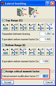
Improvements in the definition of lateral buckling moment coefficients (as of the 2011.a version)
The C1 coefficient for the lateral buckling critical moment can now be defined. Generally speaking, each code offers specific values for these coefficients associated with different bending moment distributions.
Faster seismic analysis (as of the 2011.a version)
An optimisation in the analysis procedure now reduces the time taken to analyse structures with applied earthquake loads.
Tel. USA (+1) 202 569 8902 // UK (+44) 20 3608 1448 // Spain (+34) 965 922 550 - Fax (+34) 965 124 950